6. OVIO Slit
The OVIO slit is a chrome-plated 1.5mm glass substrate and has 12 positions/widths:
Position |
Size |
|---|---|
1 |
10 microns |
2 |
20 microns |
3 |
30 microns |
4 |
40 microns |
5 |
50 microns |
6 |
70 microns |
7 |
100 microns |
8 |
150 microns |
9 |
200 microns |
10 |
300 microns |
11 |
500 (Shutter) |
12 |
700 microns |
The 500 micron (next to largest size) is blocked to be used as a simple shutter to allow taking zero and dark imagess during the daytime.
The slit disc thickness is 1.5 mm.
The slit length is 6mm which is larger than most commercial spectrographs. Benefits are easier placement of targets in the guide camera field of view and greater coverage of extended objects.
We are testing the orientation of the slit with respect to the sky. Shiny toward the grating produces a caustic
We briefly investigated the idea of reversing the slit in its holder such that the mirrored side faces the incoming beam. We found that the guide image was noticeably improved in briightness and that secondary images associated with bright stars were removed.
We did not detect any degradation in the recorded spectra, however, we have maintained the convestion of a “reversed” OVIO wheel for the present until we can investigate further.
The following images show a white light bench test of both orientations.


We also investigated the Fraunhofer diffraction pattern as it emerges from the spectrograph side of the slit because theory predicts that this will cause a degradation in overall spectra SNR due to stray light patterns withion the spectrograph body.
INSERT IMAGE - Waynes diffraction pattern.
This is shown in the attached image which is a highly magnified view of the slit taken from the science camera with the grating replaced by a mirror in the zeroeth order.

The fringe pattern can clearly be seen. Approximately 95% of the signal is contained within the first lobe. Additional lobes will cause noise in the signal through loss of collimation and focus.
We remedied this by inserting a baffle behind the OVIO mounting such that the width of the baffle exit pupil removed the unwanted lobes. This appreciably improved the sharpness of the spectral calibration lines.
Since this effect is clearly dependent upon wavelength and the focal ratio of the incoming beam a compromise baffel exit pupil width must be allowed to accomodate both the red and blue ends of the spectrum.
In addition, a baffle must be made for each desired telescope focal ratio. The baffles are easy to modify and fit as a 3D printed part.

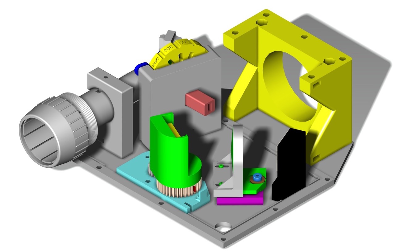
The position of the baffle is shown in the following figure. It can be seen as the red protrusion attached to the rear of the OVIO wheel mount.
A development for the FS2 will be a motorised selectable slit wheel.